autocad civil 3d drawing settings dialog box
Use this dialog box to change the drawing clarification, specify simple transformation settings, or define salve back extents.
To modify settings for a drawing, select the cartoon in the list. Enter the new information in the fields in the dialog box. When you lot cease, click Apply. You can then select a new drawing.
Specify the transformation of objects in the source drawing as they are brought into the current drawing. AutoCAD Map 3D toolset stores this data with the current drawing. The source drawing does not change. This feature is useful if you desire to overlay drawings or tile them.
- Active Drawings list
-
Select the drawing to change.
This list displays all the agile drawings in the cartoon set. If a coordinate system code is assigned to the drawing, that code is displayed in the left column.
- Filter
-
Select Filter to turn on the current cartoon filter.
When the filter is on, only drawings that match the filter are displayed. If the parent cartoon of a nested cartoon is filtered, the nested drawing is not displayed, even if it matches the filter.
To create or change the filter, click Filter. In the Drawing Fix Display Filter dialog box, you can create carve up filters for file names and descriptions.
- Drawing Description box
-
Enter a new clarification for the selected cartoon.
Descriptions brand information technology like shooting fish in a barrel for you to remember what is in a drawing. If a clarification is assigned to the drawing, it appears in the drawing list instead of the file name.
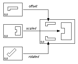
Simple Transformation area
Specify the transformation of objects in the source drawing every bit they are brought into the electric current cartoon. AutoCAD Map 3D toolset stores this information with the current drawing. The source drawing does not change. This feature is useful if you lot desire to overlay drawings or tile them.
If the certificate has a coordinate organization lawmaking assigned to information technology, y'all cannot use the simple transformation section.
When objects are saved back to their source drawings, their original scale, offset, and rotation are restored. To permanently transform an object, utilize the ADETRANSFORM command.
- Elementary Transformation
-
Plough the simple transformation settings on and off.
When cleared, the settings are not used.
If the document has a global coordinate organisation code assigned to information technology, you cannot utilize the elementary transformation option.
Simple transformations let you tile, scale, or overlay drawings.
- Scale box
-
Specify the modify in scale of objects from the source cartoon to the current cartoon.
Enter a existent number. For example, enter 2 to double the size of objects, or enter .5 to halve the size of objects.
- Rotation box
-
Specify the rotation of objects from the source drawing to the current drawing.
Enter an bending. For example, enter 90 to rotate objects ninety degrees in the current direction. (To view or change the current direction, open the source drawing and use the DDUNITS command.)
- Showtime (10,Y) box
-
Specify the offset of objects from the source drawing to the current drawing.
Enter two real numbers (1 for 10 and i for Y), separated past a comma. For instance, enter v,-iv to offset objects v units to the right and 4 units down. (To view or modify the current unit, open up the source cartoon and apply the DDUNITS command.)
If you specify save back extents for the drawing, those extents are also kickoff.
- Pick <
-
Display the cartoon, where you tin specify points to decide the calibration, rotation, and offset.
- The divergence between the quondam base of operations bespeak and the new base point is the offset for objects in the source drawing.
- The deviation in angle betwixt the ii one-time points and the 2 new points is the rotation. 0,0 is the base point for the rotation.
- The ratio of the length between the two new points to the length betwixt the two old points is the alter in scale.
Save Back Extents area
Specify the area that is saved back to the source drawing. Past specifying save back extents, you can prevent boundaries from expanding and intruding on the boundaries of adjacent drawings. These relieve dorsum extents are stored with the source drawing.
- Save Back Extents list
-
View the coordinates of the current save back extents.
- Define <
-
Display your drawing, where you can select points to specify the relieve back extents.
Note:
This displays the electric current window. To view or change the extents for the entire drawing, zoom to drawing extents before starting this control. To zoom drawing extents, click
 . Notice
 - Testify <
-
Brandish the current save dorsum extents in the electric current drawing. Save back extents are indicated by a dotted line.
Note:
This shows only the extents displayed in the current window. To view the extents for the unabridged drawing, zoom to drawing extents before starting this command. To zoom cartoon extents, click
. Find - Reset
-
Reset the values to the original drawing extents adjusted for uncomplicated transformations.
The default save back extents are the extents of the source drawing adjusted for elementary transformation.
Source: https://knowledge.autodesk.com/support/autocad-map-3d/learn-explore/caas/CloudHelp/cloudhelp/2020/ENU/MAP3D-Use/files/GUID-4E1C324E-8A27-4F5E-A233-D2DA225FAA15-htm.html
0 Response to "autocad civil 3d drawing settings dialog box"
Postar um comentário